
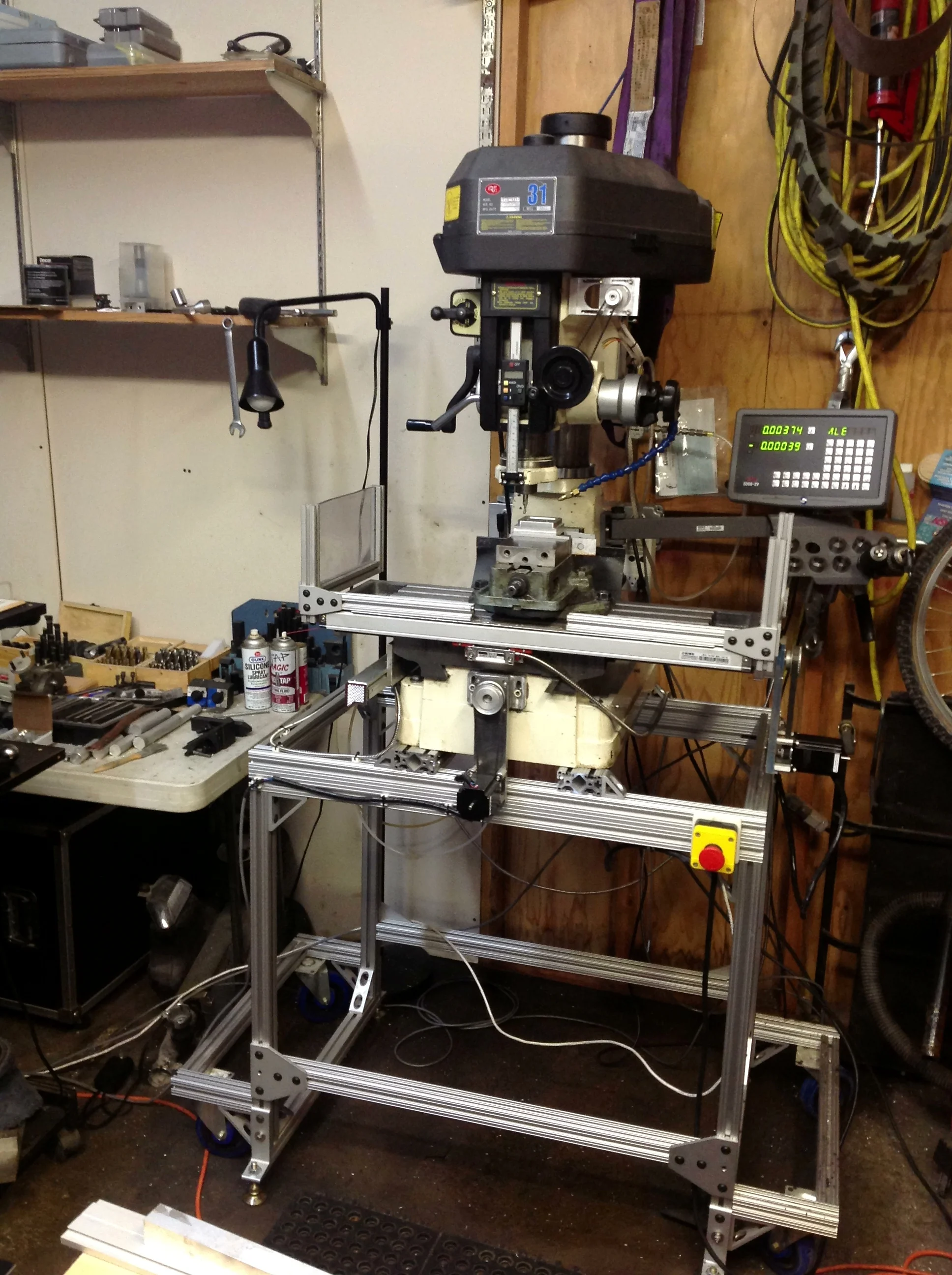
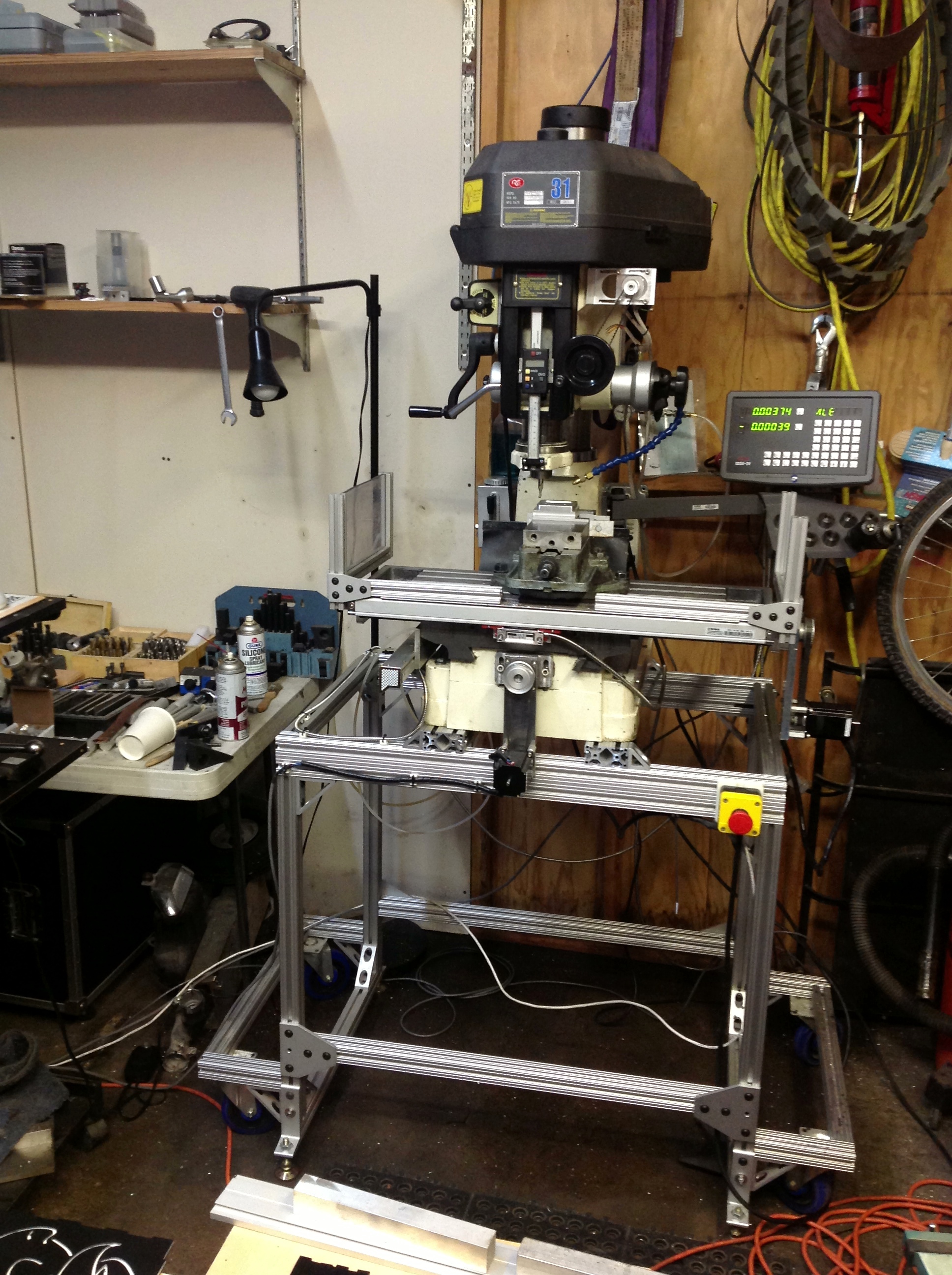
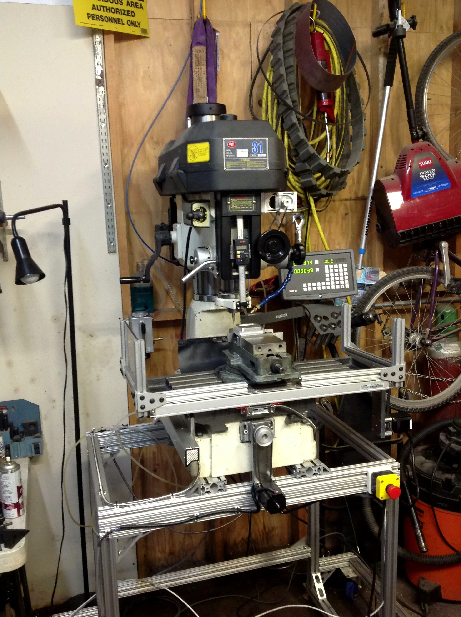
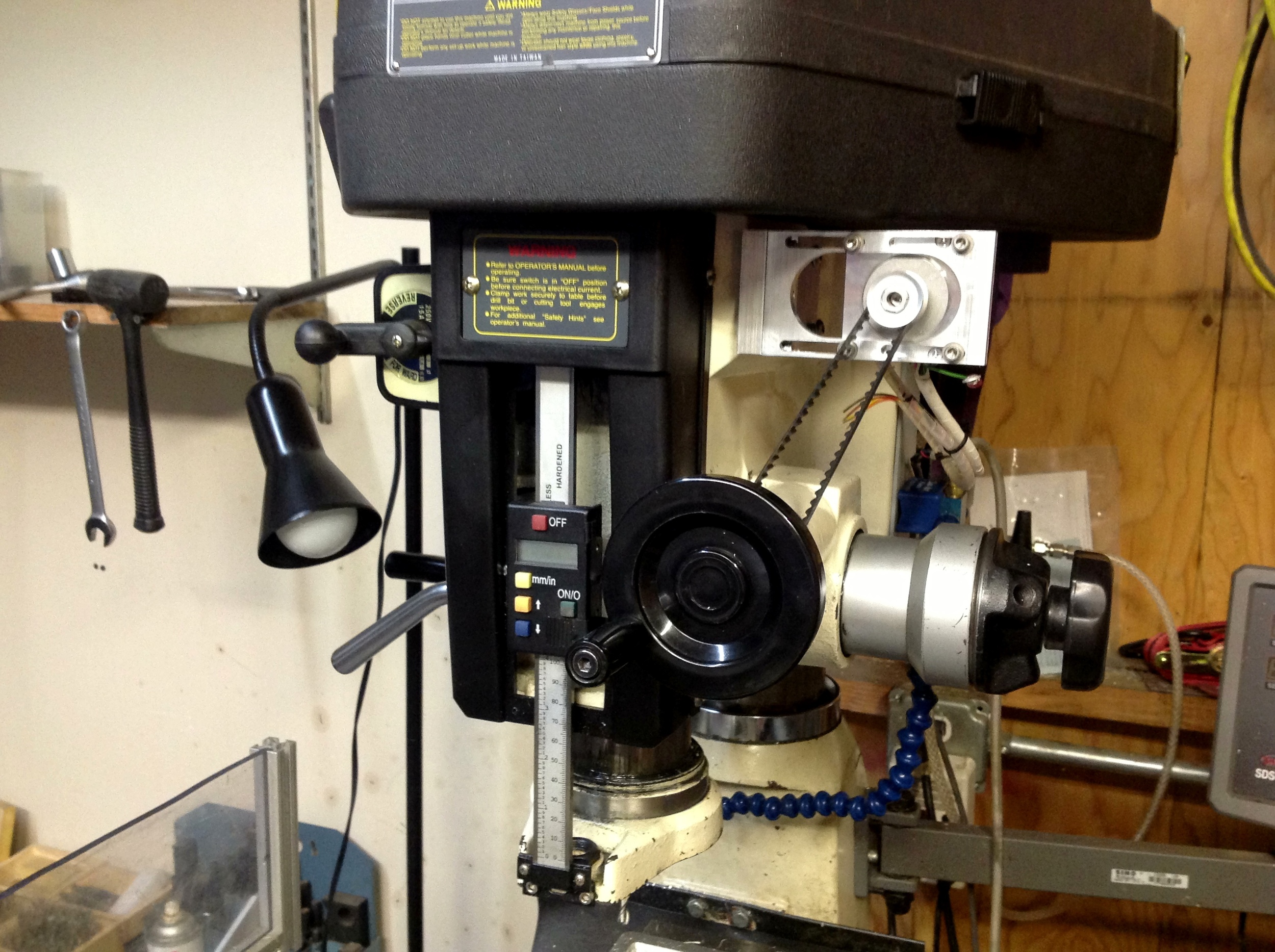
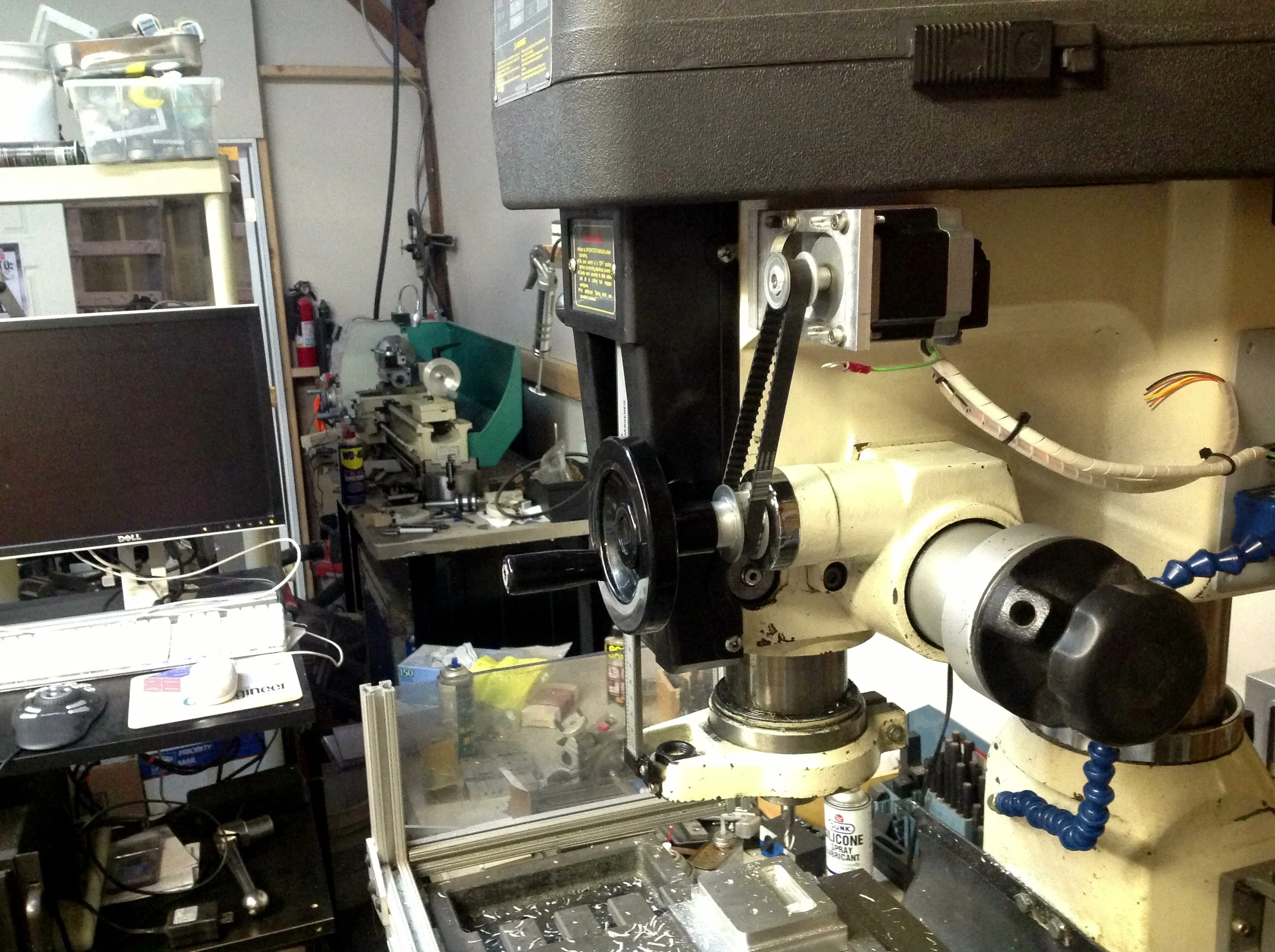
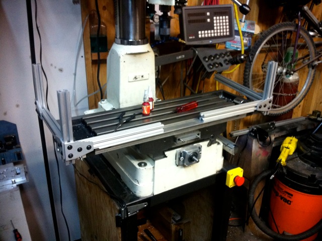
I've been upgrading my RF-31 round column milling machine to CNC control with ball screws and stepper motors. I'm documenting things as I go along.
There are a number of other mills based off the RF-31 design and I believe the square column mills like the RF-45 look like they have the same base, so the dimensions on the parts (and screw lengths) should transfer directly, but you should double check.
I did all the CAD work in Solidworks. and I’m including e-drawings versions of the solid models.
Ball Screw Upgrade
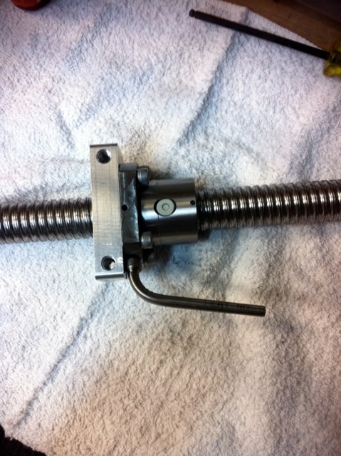
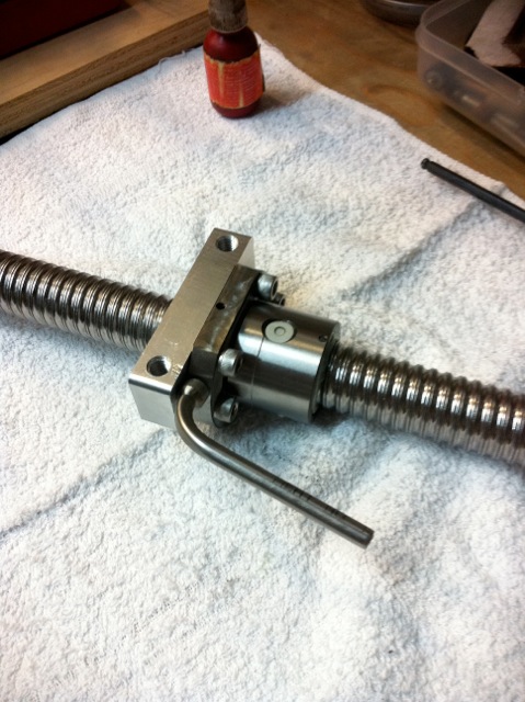
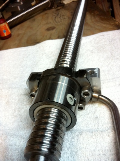
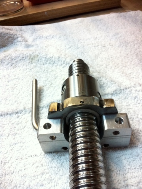
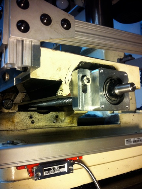
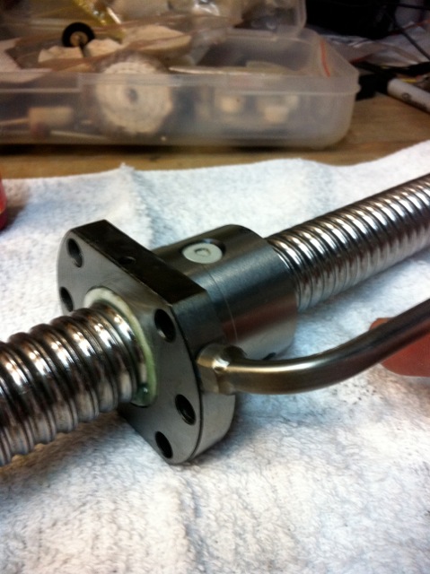
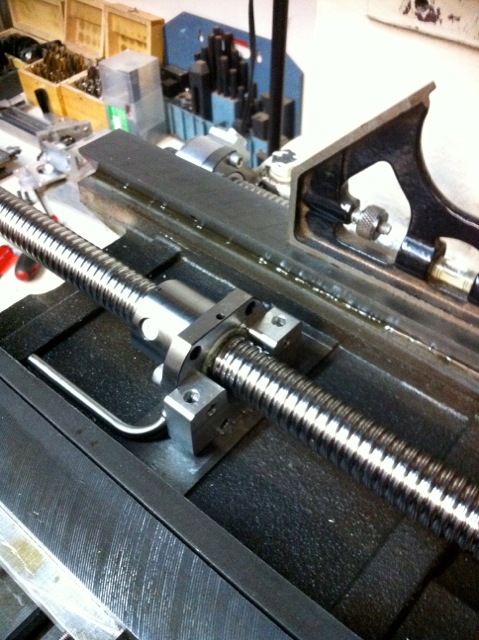
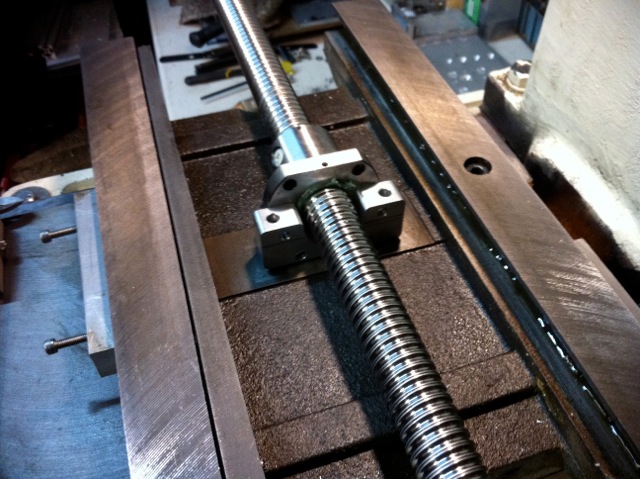
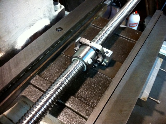
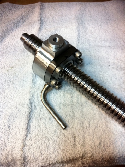
The screws I purchased were off of e-bay from linearmotionbearings2008, and look to be direct copies of NSK ball screws. I got ones that are 25mm dia x 5mm pitch with one end machined for a fixed bearing and shaft for attaching the motor, and the other end for a floating (single) bearing. The X-Axis is 807mm total length (734mm threaded length + 73mm ends) and the Y-Axis is 434mm total length (361mm threaded length + 73mm) If you request custom lengths (like I did) he will gladly make them for you.
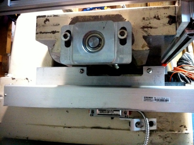
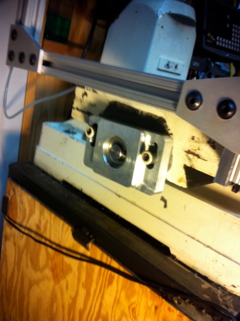
The bearings included were marginal, so I purchased new ones from McMaster Carr:
6677K51 Metric Steel Tapered-roller Bearing, For 15 Mm Shaft Diameter, 42 mm Outside Diameter
5972K358 Metric Ball Bearing for 15mm Shaft Diameter, 32mm Outside Diameter, 9mm Thickness
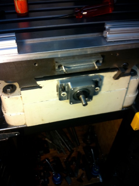
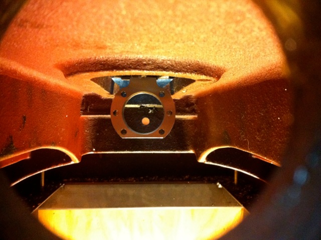
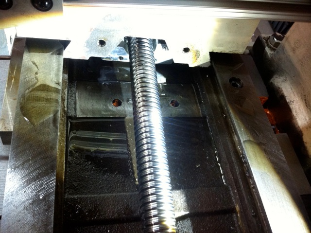
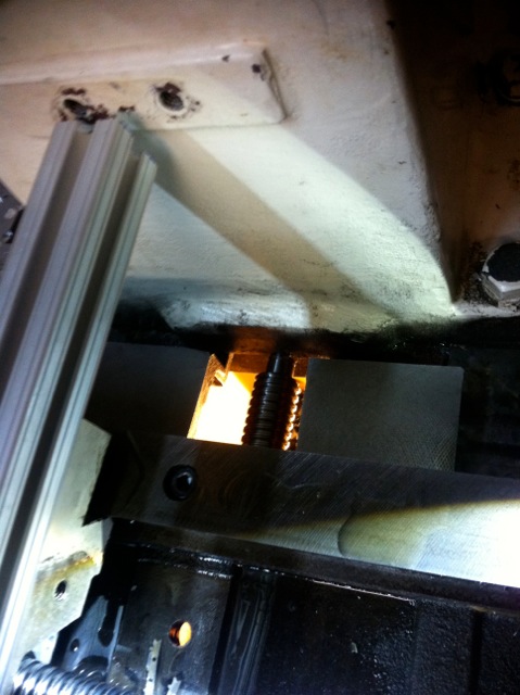
In retrospect, I would suggest getting the next diameter smaller screws - the space underneath the X-Table is really tight, and I had to grind down the top part of the ball nut to clear the table. The nuts are fully hardened steel and not easily machined.
For lubrication, I drilled out a couple of M4 metric screws and welded on some 1/4” stainless tubing and put those in where the zerk fittings on the ball nuts would go.
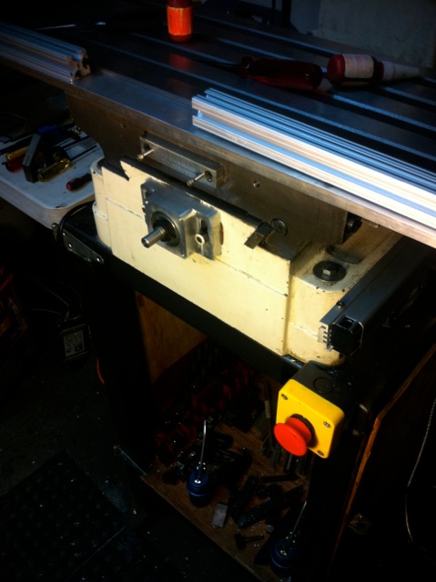
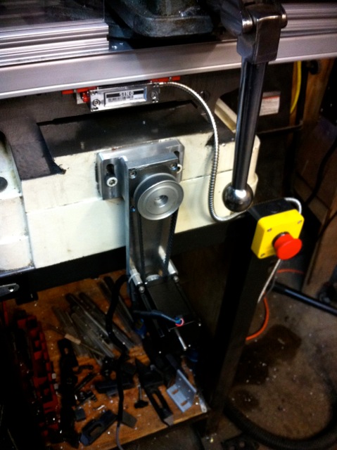
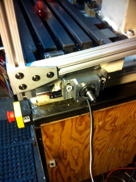

Motor Controls
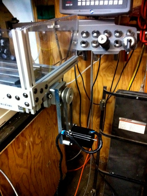
I built a 4-axis motor control system using a pair of Applied Motion 2035XD stepper drives that I found at a surplus auction a few years back, and DIN rail mounted 24VDC power supplies housed in a repurposed rack-mount PC case. The motors are high-torque NEMA 23 stepper motors from Lin Engineering. The drives are controlled using Mach3 on an old Sony Vaio laptop
Having the fourth axis will let me add a rotary table into the mix later.

CAD Models of the upgrades are here.